
LED chips are literally everywhere. The phone in your pocket, smart display on your kitchen counter, tiny blinking light on your router. Every single one of those devices depends on LED chip technology to function. And if you're on the engineering or product side of consumer electronics, picking the right LED chip isn't just some box you check off a list. It directly affects how your product performs, how much power it pulls, and whether the person using it walks away happy or frustrated.
The problem is that sourcing and integrating compatible LED chips is genuinely messy. Product data is scattered, compatibility standards aren't always clear, and the number of options out there is overwhelming. This article is meant to cut through all of that. You'll get a solid understanding of how LED chip technology actually works, a breakdown of the major SMD LED categories and where they fit in real-world designs, a clear look at why PLCC LEDs are a go-to for consumer tech, and a step-by-step process for finding and integrating the right LED chips into your existing designs without blowing up your timeline.
Understanding LED Chip Light Technology from the Ground Up
An LED chip light is a semiconductor device that converts electrical energy directly into light through electroluminescence. When current flows through the semiconductor material, electrons recombine with electron holes, releasing energy in the form of photons. This process generates minimal heat compared to traditional incandescent sources, making LEDs fundamentally more efficient at turning watts into usable illumination.
But for anyone designing electronics, efficiency is really just the starting point. LED chips work across a wide voltage range, respond to control signals almost instantly, and can scale from tiny indicator lights to full display backlights. Their compact size makes them easy to fit into densely packed PCB layouts where every millimeter counts. Their long lifespan cuts down on maintenance and keeps warranty headaches to a minimum.
A few terms come up constantly when talking about LED chips and you'll want to have them down. Forward voltage is the minimum voltage needed to get the LED to turn on. Luminous intensity, measured in millicandelas, tells you how bright it is. Color temperature in Kelvin tells you whether white light looks warm or cool. Viewing angle tells you how widely the light spreads out from the source. Thermal resistance tells you how well the chip handles heat over time, which matters a lot for long-term reliability. Once you have these terms locked in, comparing options and reading datasheets becomes a whole lot less painful.
SMD LED Categories and How They Actually Fit into Your Design
Surface-mount LEDs come in standardized packages, and the naming convention is pretty intuitive once you see it. A 3528 package measures 3.5mm by 2.8mm. A 5050 measures 5.0mm by 5.0mm. Those numbers directly reflect the trade-offs between footprint, light output, and power draw that you'll be balancing against your PCB space and thermal budget.
The 3528 is a reliable workhorse for low-profile applications. Its small body and modest power draw make it a natural fit for notification indicators on wearables, keyboard backlighting, and thin-bezel display edges where component height is tight. The 5050, on the other hand, packs three LED dies into a single package. That gives you either RGB color mixing or significantly higher output in a single color, making it the right call for full-color status displays, ambient lighting strips in smart speakers, and decorative UI elements in consumer hubs. The 2835 has built a strong reputation in high-efficiency backlighting for tablets and e-readers because it delivers better lumens per watt in a slim profile.
Picking the Right Subtype Comes Down to Four Things
Power consumption, forward voltage range, luminous intensity, and thermal resistance. The 2835 typically runs at lower forward voltages and handles heat well, which makes it a smart choice for battery-powered devices where heat buildup shortens component life. The 5050's three-die setup needs more careful thermal pad design on your PCB, but it gives you the color flexibility that modern consumer tech products increasingly demand. If you're working on miniaturized designs like smartwatches, wireless earbuds, or compact IoT sensors, the 0603 and 0402 packages push size limits even further, giving up some raw brightness in exchange for near-invisible integration.
The right approach is to pull the datasheet, cross-reference the maximum continuous forward current against your driver circuit's output, and confirm the package's thermal resistance stays within safe limits at your expected operating temperature.
PLCC LEDs: Why Consumer Tech Keeps Coming Back to Them
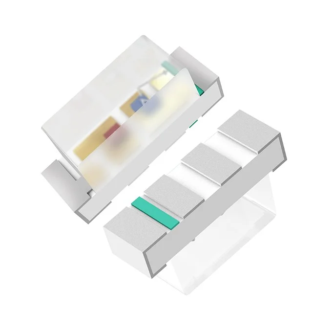
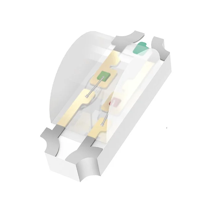
PLCC stands for Plastic Leaded Chip Carrier. These are surface-mount components housed in a molded plastic body with leads extending underneath the package. That structure gives them a low, stable profile that sits flush against the PCB surface, which is exactly what automated pick-and-place assembly lines need. The reflective cavity built into the package pushes light output upward efficiently, and the plastic housing provides mechanical protection that bare-die alternatives just can't offer. Compared to through-hole LEDs, PLCC packages skip the drilling step entirely and cut down assembly time, which adds up to real cost savings when you're manufacturing at scale.
In consumer tech, PLCC LEDs show up wherever reliable, compact light output is non-negotiable. Power indicators on laptops and wireless chargers, status lights on smart home devices, backlight arrays in remote controls. Manufacturers like HQG OPTO have built PLCC lamp bead lines specifically for these applications, where tight color uniformity and predictable forward voltage matter because inconsistency shows up visually and hurts your brand. Automotive interior applications have also adopted PLCC LEDs heavily for dashboard indicators and ambient cabin lighting, where vibration resistance and temperature stability aren't optional, they're required.
Where PLCC LEDs really stand out compared to standard SMD packages is long-term assembly reliability. The molded housing handles reflow soldering profiles without putting stress on the die, and the standardized footprint simplifies PCB layout across multiple product generations. If your team is managing frequent design refreshes, that footprint consistency alone cuts re-qualification time significantly.
What Industrial LED Applications Can Teach You
Industrial environments push LED components far beyond anything consumer electronics typically have to deal with. Factory machinery, outdoor signage, mining equipment, transportation infrastructure. These applications need LEDs that hold up under sustained vibration, wide temperature swings, and exposure to dust, moisture, and corrosive materials. A consumer device sits in a temperature-controlled room. An industrial LED might cycle through freezing nights and scorching midday heat for years without anyone being able to replace it. That reality shifts the entire design priority set toward durability and consistency rather than pure cost optimization.
High-intensity output is a baseline requirement in a lot of industrial settings. Warehouse signaling arrays, traffic management displays, and machine vision lighting systems need luminous intensity levels that make consumer indicator applications look tiny. Manufacturers in this space engineer LEDs with reinforced die-attach materials, higher forward current tolerances, and encapsulants that resist UV degradation. Regulatory compliance adds another layer on top of all that, with industrial LEDs often required to meet IEC, UL, or RoHS standards covering electrical safety, hazardous materials, and electromagnetic compatibility.
There's real value in studying how industrial LED design works even if your products never go near a factory floor. The thermal management strategies developed for high-duty-cycle industrial lighting translate directly into longer lifespans for consumer products. Adopting tighter binning standards reduces the visual variation across production runs that quietly erodes brand quality perception. The core lesson industrial applications offer is this: treating durability as a design input from the beginning, rather than an afterthought, pays off every time.
How to Actually Find and Integrate Compatible LED Chips
Sourcing compatible LED chips gets a lot more manageable when you treat it as a structured process rather than a frantic search whenever a project deadline is coming up. The challenge isn't just finding components that meet spec on paper. It's confirming they integrate cleanly into your existing design without triggering costly redesigns or disrupting your assembly line.
A Step-by-Step Process That Actually Works
Start by locking down your design parameters before you open a single supplier catalog. Write down the operating voltage range your driver circuit delivers, the maximum forward current your PCB trace width can handle, the physical footprint constraints your enclosure imposes, and the target luminous intensity or color temperature your product needs. Those four inputs immediately eliminate incompatible options and give you objective criteria for comparison rather than gut feelings.
Next, research available LED chips using supplier datasheets as your primary source, not marketing summaries. Cross-reference the forward voltage range, thermal resistance values, and binning classifications against your documented parameters. Reputable distributors like Mouser, Digi-Key, and direct manufacturer portals including specialized LED lamp bead suppliers like HQG OPTO provide downloadable datasheets with the detail level you need for real comparison. Pay close attention to the bin code system, which defines the tolerance bands for color and brightness within a production lot.
Before you commit to volume orders, validate compatibility through prototyping. Build a small test circuit using your target driver and measure actual forward voltage, current draw, and junction temperature under sustained operation. Thermal imaging during this phase reveals hotspots that datasheet values alone won't show you. Simulation tools like SPICE can fill in gaps for edge cases.
Once the component is validated, implement it into your final design and run system-level testing, including EMC screening if regulatory compliance is on the table. Document your qualification results and keep a qualified vendor list so future sourcing decisions don't start from scratch every time.
Bringing It All Together
Choosing the right LED chip is one of the most consequential decisions in electronics product development. It shapes energy efficiency, visual performance, manufacturing cost, and long-term reliability all at once.
SMD LED categories from the compact 2835 to the versatile 5050 offer distinct trade-offs in footprint, brightness, and thermal behavior that map directly to specific applications. PLCC LEDs bring assembly consistency and optical predictability that make them a trusted choice wherever visual uniformity and manufacturing efficiency matter. Industrial LED applications show that durability and thermal discipline aren't optional extras. They're design inputs that extend product lifespan and protect your brand.
The step-by-step integration framework laid out here turns a fragmented sourcing challenge into a repeatable, structured process. Lock down your parameters first. Validate datasheets rigorously. Prototype before committing to volume. Document your qualification results. Follow that path and compatible LED chip integration stops being a recurring obstacle and starts becoming something your team actually has under control.
Disclaimer: This post was provided by a guest contributor. Coherent Market Insights does not endorse any products or services mentioned unless explicitly stated.


